The XOR gate is also called the exclusive OR gate. In this article, I will show 4 different ways it can be built on a breadboard using individual transistors. This gate is similar to the OR gate but when both inputs are on the output is off. That is why is the exclusive OR gate as in only for the true OR cases. In the simplest design, only 5 transistors are needed. However in order to send an output 6 transistors will be needed. The XOR gate can be built with NAND gates but 8 transistors are needed. It can also be built with NOR gates and 10 transistors would be needed.
XOR Gate 1
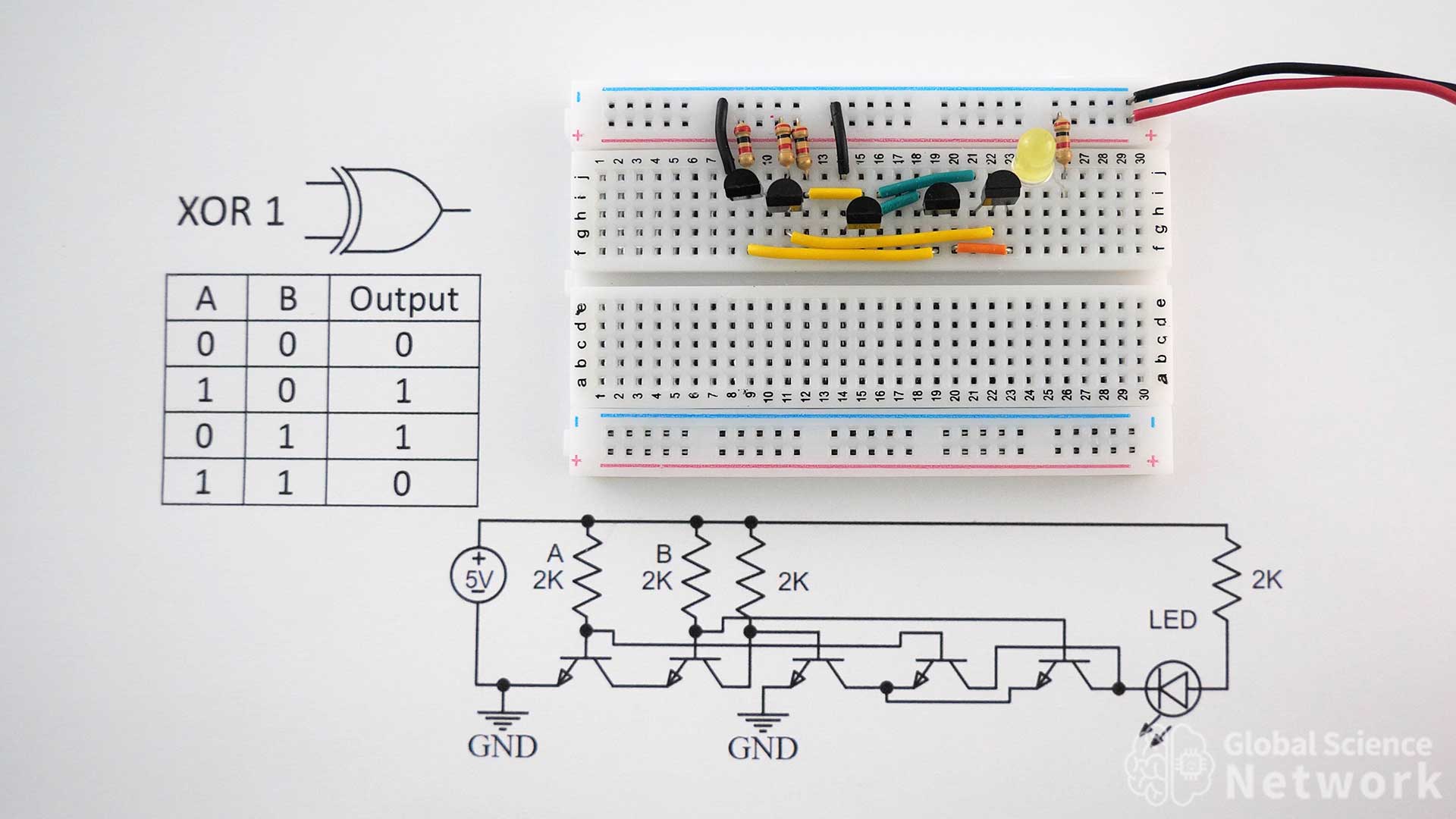
The photo above shows a simple XOR gate that uses 5 transistors. In the layout inputs A and B are both on which is why the LED is off. The two resistors on the left are the two inputs. Different color wires help to see the connections. If there is any ambiguity in the placement of wires the circuit diagram can be referenced. The gate design is a NAND gate on the left two transistors, a switch for the middle transistors, and an OR-like gate for the last two transistors. Looking at the configuration in the photo the current from the far right resistor can not reach the ground to the left so the LED is off. This is the case because all of the current from the first resistor from the left is going to the first ground. When this happens the switch is off because there is not enough voltage going into the base of the third transistor.
When one input is on current is able to flow from the far right transistor to the second ground. Finally when both inputs are off the output is off because the current does flow into the base of the OR gate transistors making it so the current can flow from the far right resistor into the second ground.

The video above shows how to build all types of logic gates. At 31:48 how to build the Exclusive OR gate is discussed at length. It is common to use XOR gates in half adders, full adders, and for other computations so this is an important gate to understand.
XOR Gate Truth Table
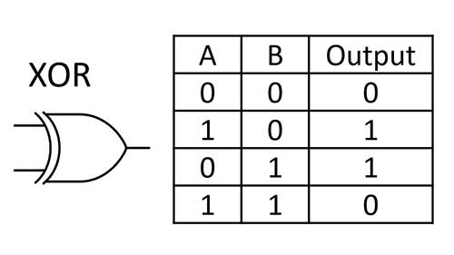
The XOR gate symbol and truth table are shown above. This table makes it clear that when both inputs are on or off the output is off. When only one input is on the output is on. I will show several different ways to make an XOR gate but the truth table will be the same for all of the cases.
XOR 1 Circuit Diagram
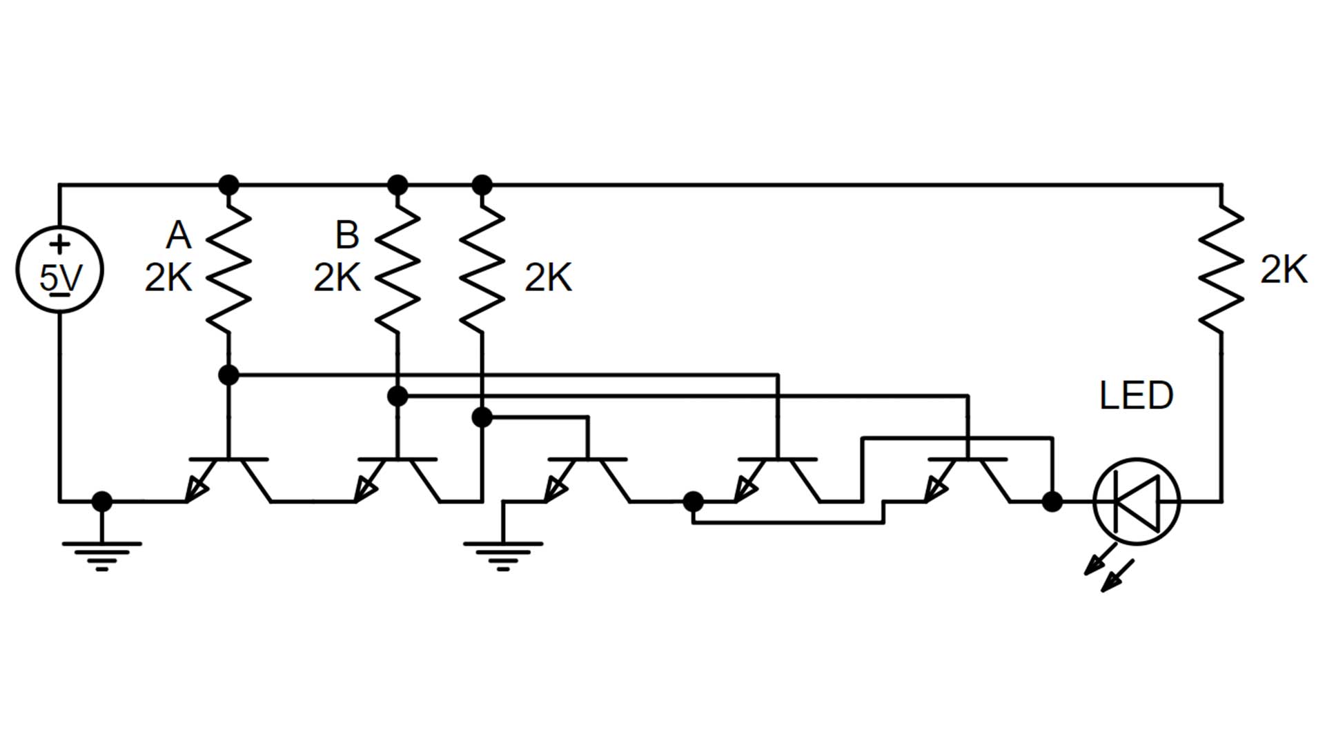
This is the circuit diagram for the first case that uses 5 transistors. Inputs A and B are on when the first two resistors are in place. Now the direction of the LED is configured so current is flowing into the circuit. This means this layout will work as a stand-alone logic gate or as a final logic gate. It will not work to send the signal elsewhere.
XOR Gate 2
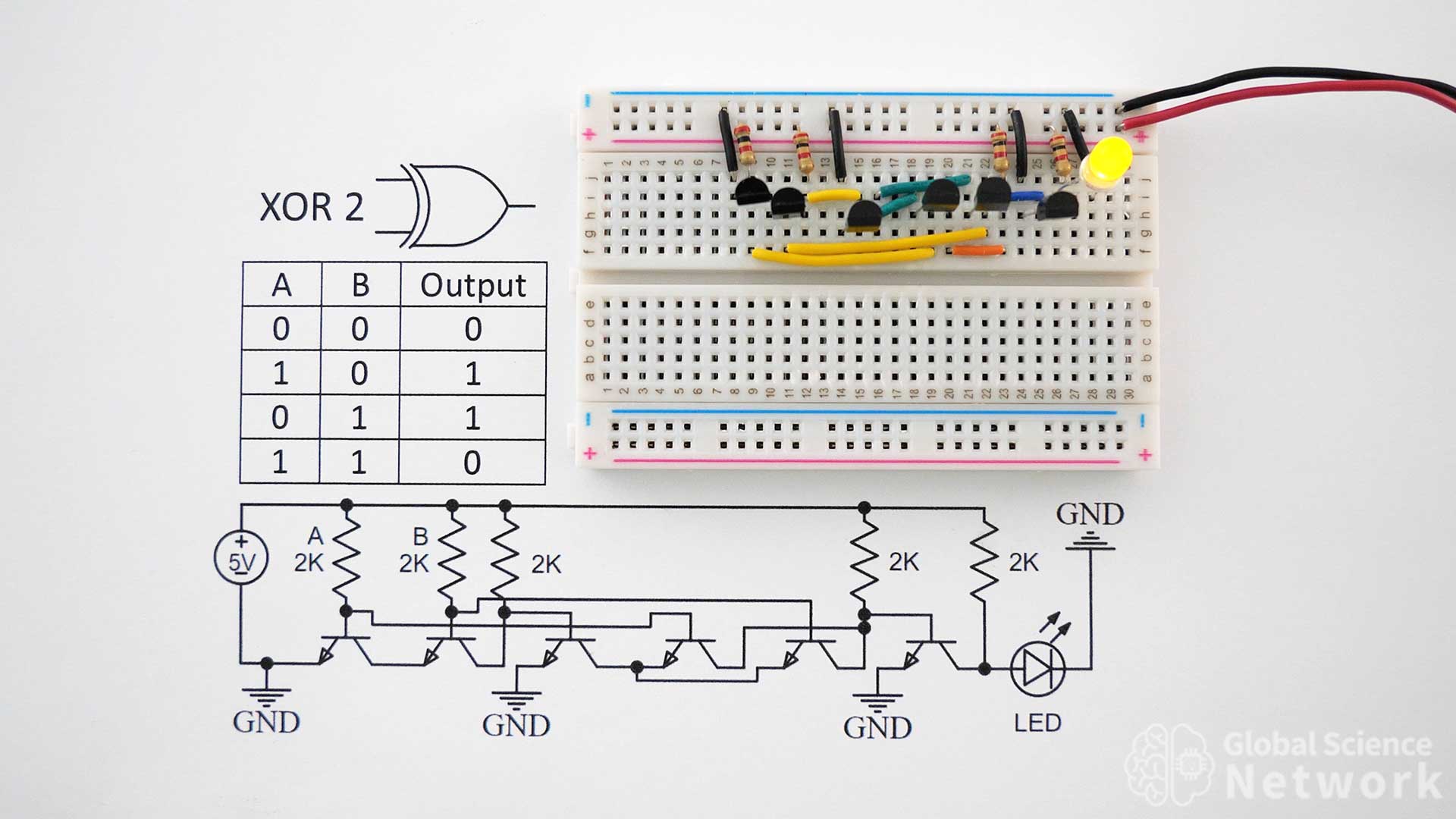
XOR Gate 2 is very similar to the first XOR gate but adds one more transistor on the right-hand side of the circuit. This makes it so that the current can be sent as an output. I would recommend building the XOR gate this way as it works in all cases and only requires 6 transistors. Note that it takes 6 transistors and will work in all cases.
XOR 2 Circuit Diagram
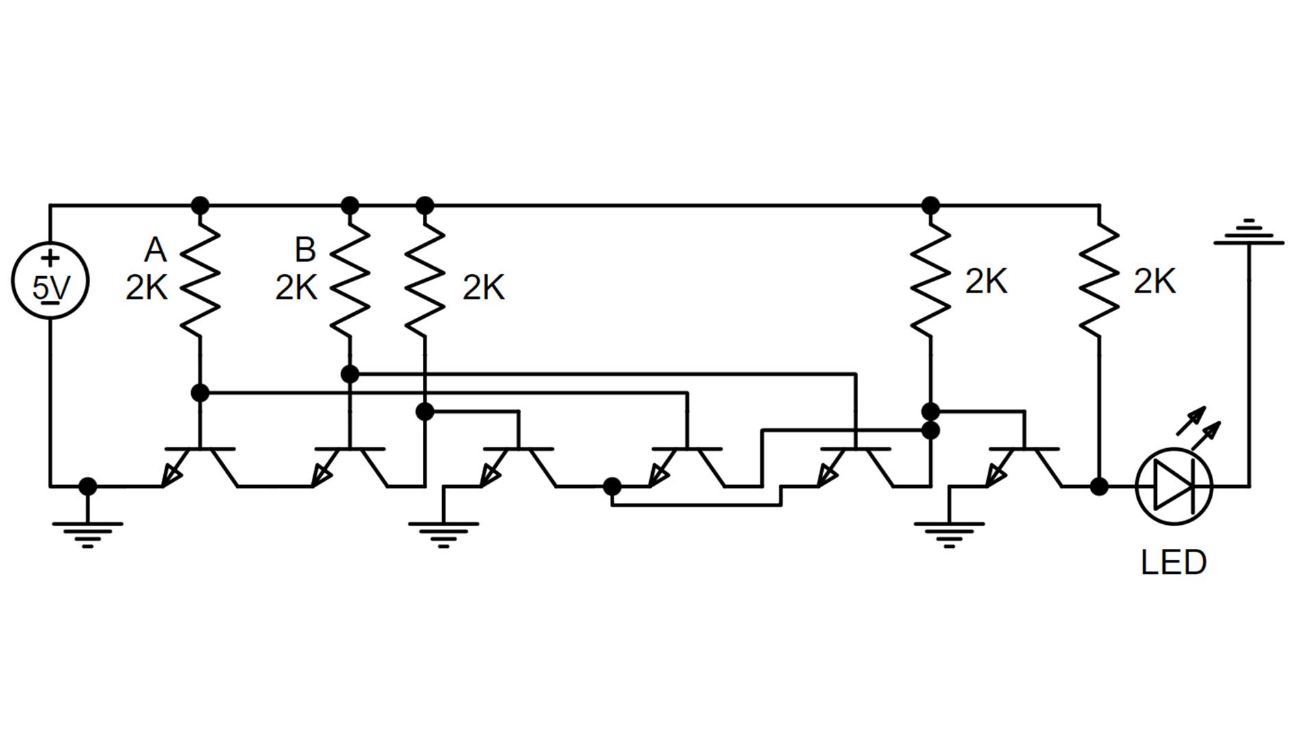
The circuit diagram for XOR gate 2 is almost the same as the first XOR gate. Now there is an additional transistor that is somewhat acting as an inverter. However, now the LED direction is flipped and the current is flowing out of the circuit. This is good as the output can be sent elsewhere. Typically it is sent to other logic gates to complete more computations.
XOR Gate Built with NAND Gates
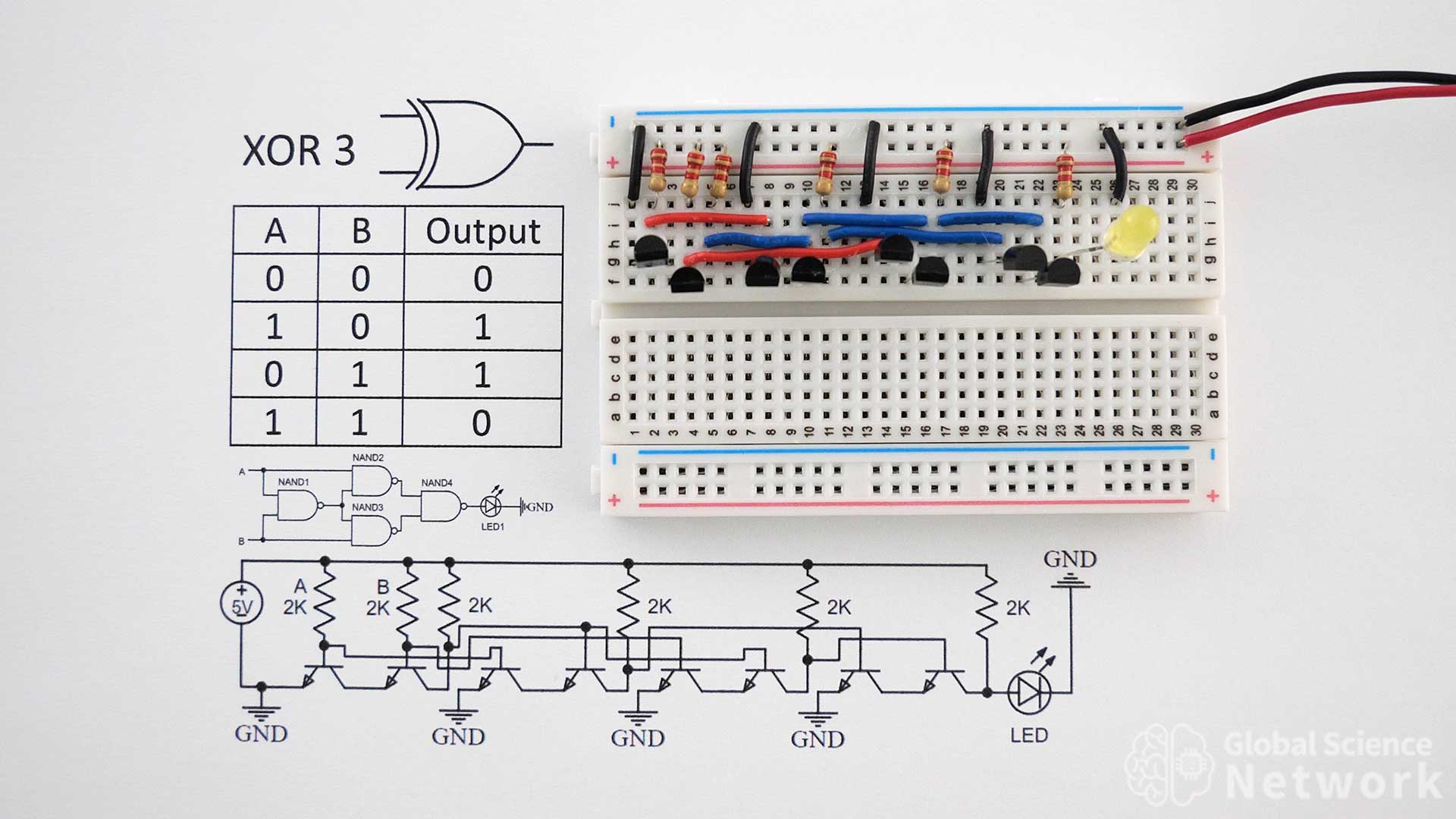
XOR gate 3 is built using 4 NAND gates. Each NAND gate requires 2 transistors so a total of 8 transistors is needed to build the gate in this configuration. Input A and input B are the first two resistors on the left-hand side of the circuit. Right now both inputs are on and the output is off, which is expected. To turn the inputs off the input resistors need to be removed. The resistor values are 2K and the circuit is powered with a 5-volt battery pack.
XOR Gate Built with NAND Gates Circuit Diagrams
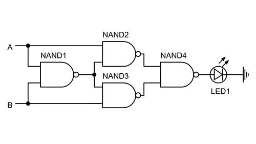
The gate-level circuit diagram is shown above. This shows how the inputs and output of each NAND gate need to be connected to make the NOR gate. At the transistor level, you get more detail including seeing the ground connections. Many times circuit designers are just using integrated circuits for the logic gates and the high-level diagram is sufficient.
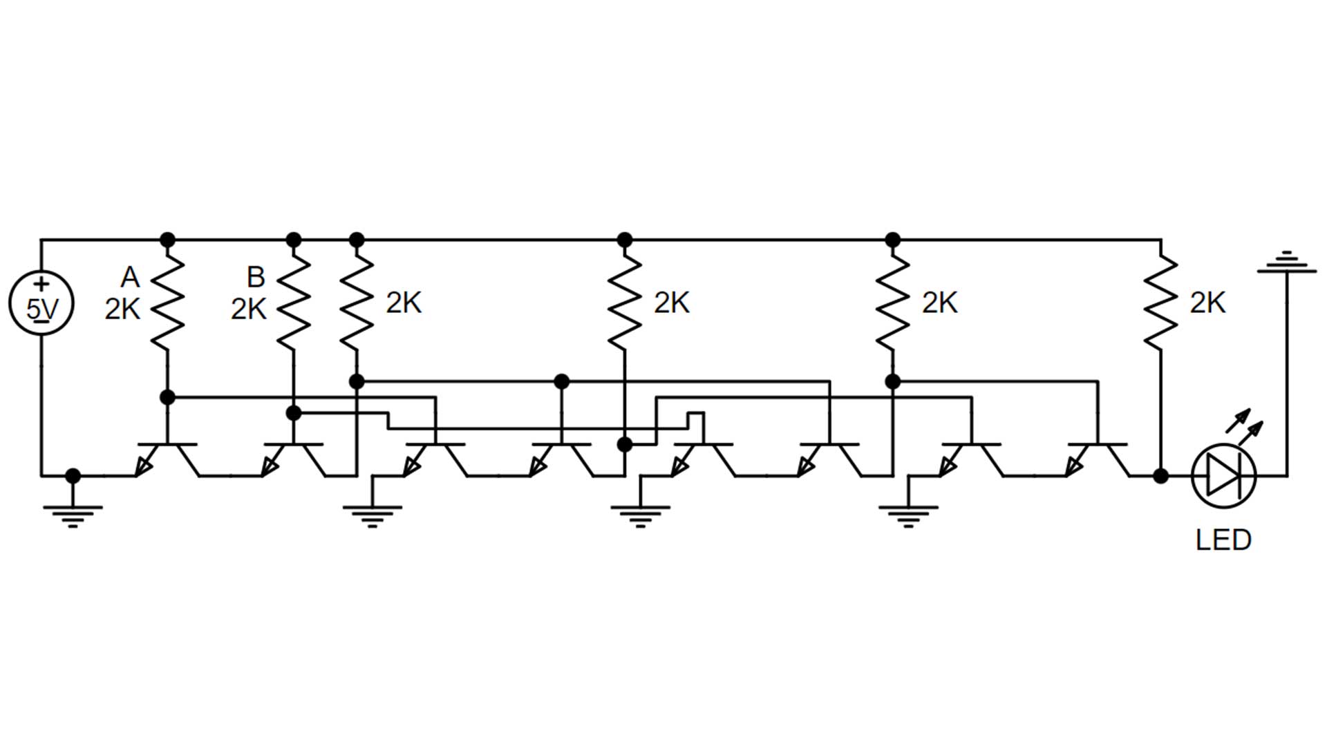
The circuit level diagram above shows component level details of this configuration. It is often easier to see how wires are to be connected by looking at the circuit diagram rather than the circuit on the breadboard. This shows the connections to the base, emitter, and collector of each NPN transistor. The transistors can be model numbers 2N2222 or 2N3904, which are both BJT transistors. All the resistors are 2K but values from 330 ohms to 2.2K would work.
XOR Gate Built with NOR Gates
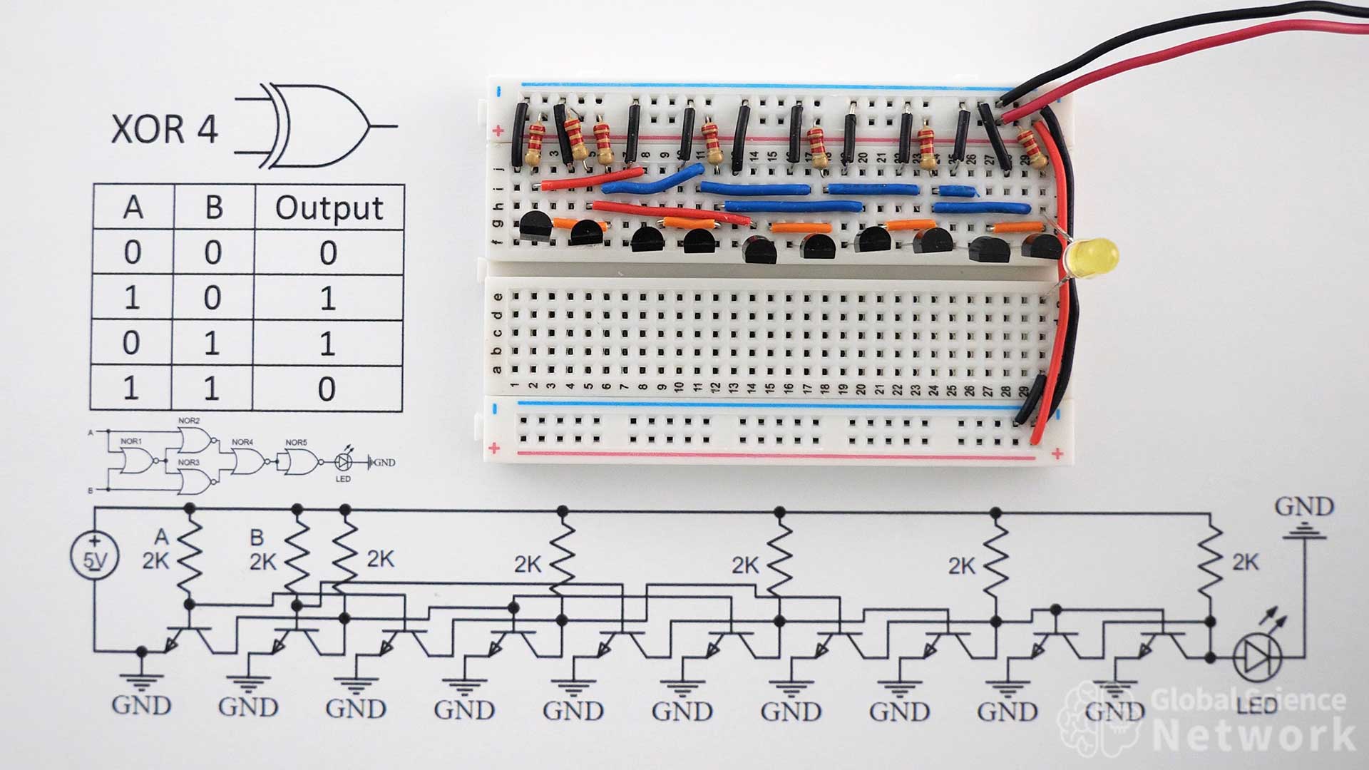
Exclusive OR gate 4 is built using 5 NOR gates. Each NOR gate requires 2 transistors so a total of 10 transistors is needed. For this reason, this is not the simplest NOR gate to implement. In most cases, it will not be used unless the computer or circuit architecture is based on the NOR gate. One example where this was the case was the Apollo Guidance Computer. There were two versions of the computer, the first used 4,100 NOR gates on separate integrated circuits, and a later version used 5,600 NOR gates.
XOR Gate Built with NOR Gates Circuit Diagrams
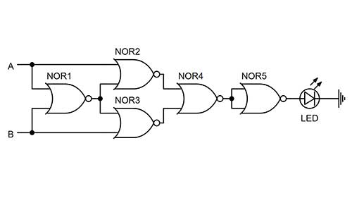
The gate level circuit diagram using NOR gates is shown above. This shows where inputs A and B should be connected as well as where the output of each gate should go. How each NOR gate is made is not detailed and each NOR gate could actually be made from four NAND gates. However, using the two transistor NAND gate is likely the best option.
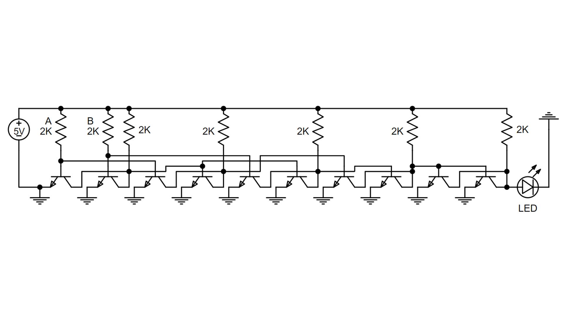
Above is the component level circuit diagram of NOR Gate 4. The circuit requires 10 NPN transistors, 7 2K resistors, and an LED. The circuit is powered with a 5 Volt power supply.

The video above shows XOR gates used in a 4-bit computer. XOR gates are used in the ALU for the subtract feature and in two of the full adders.

Cody started the Global Science Network with the idea people should be focusing more time, energy, and resources on useful projects. He has a bachelor’s degree in aerospace engineering and a master’s degree in mechanical engineering. Cody has worked for the US federal government, a university, a large corporation, small businesses, and for himself. He has done human brain computer interface research and is currently working towards creating non-biological human consciousness.